


| Quantity: | |
|---|---|


SF-SP12-D12.5 Dimmable 12MP
SINCEREFIRST
This 12MP autofocus USB endoscope camera module is designed for OEM inspection equipment that needs detailed imaging across changing working distances. Its 1/3.06-inch CMOS sensor provides a maximum image size of 3840 × 3104, while the autofocus system covers targets from approximately 3.5cm to infinity.
Eight white SMD LEDs surround the lens and support adjustable brightness for dark cavities and reflective surfaces. An integrated DSP handles image processing, and the USB 2.0 UVC interface simplifies connection to a compatible host. The module is available as a compact bare configuration and as a larger steel-shell configuration for projects requiring additional mechanical protection.
The module can be evaluated for industrial borescopes, maintenance tools, research imaging systems and medical or veterinary equipment development. The final equipment manufacturer remains responsible for validating image performance, sealing, electrical safety, materials, cleaning or sterilization procedures and applicable regulatory requirements.
12MP CMOS imaging with a maximum 3840 × 3104 output
Autofocus from approximately 3.5cm to infinity
Up to 30fps with a supported compressed-output configuration
80.9° diagonal field of view for balanced coverage
F/2.2 aperture for close-range illumination efficiency
Eight dimmable 4500–5000K white LEDs
Integrated DSP with AEC, AGC and AWB image controls
USB 2.0 UVC connection for compatible host systems
Bare-module and steel-shell structure options
5V supply and labelled hardware snapshot connection
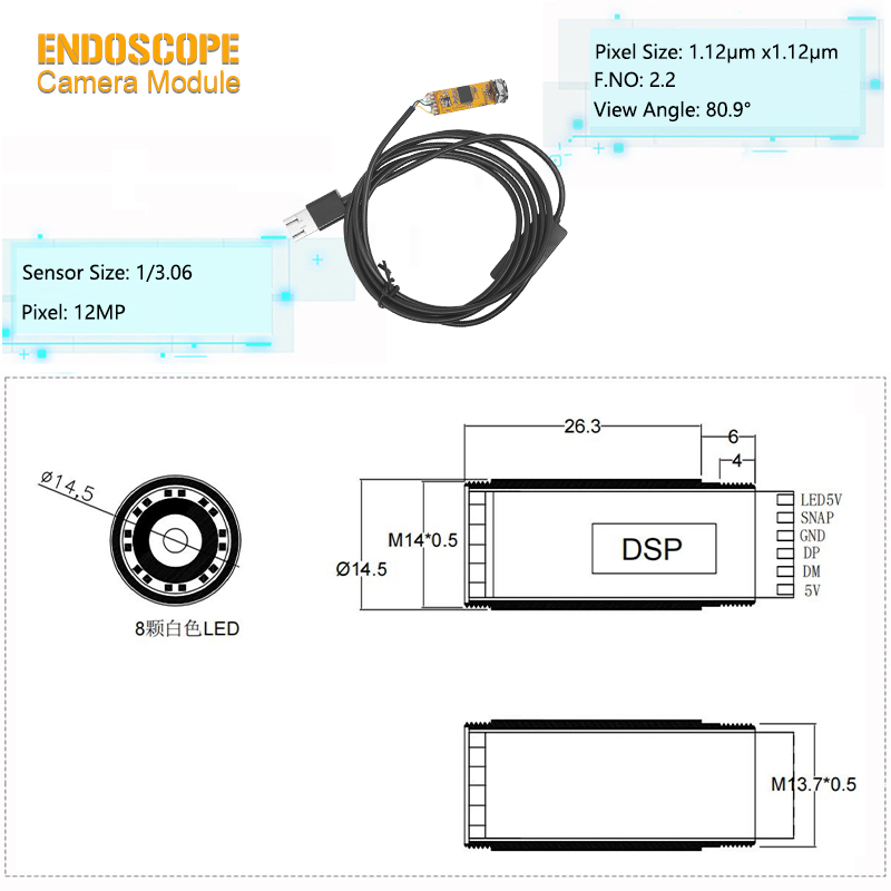
The 1/3.06-inch CMOS sensor uses a 1.12μm × 1.12μm pixel size and provides up to 3840 × 3104 output. This gives the operator more image information for documenting surfaces, comparing components and reviewing small visual features than a lower-resolution module can provide at the same framing.
Resolution alone does not determine whether a defect can be identified. Lens performance, working distance, surface contrast, illumination, compression, display scaling and movement all affect the visible result. A sample should be tested with the real target, required viewing distance and intended host software before the image specification is approved.
The module uses 10-bit ADC processing. Automatic exposure, automatic gain and automatic white balance help the system respond to changing brightness and color conditions, but OEM image tuning may still be needed when the target materials or inspection environment differ substantially from a general test scene.
The listed maximum frame rate is up to 30fps at 12MP when a supported compressed video configuration is used. Actual performance depends on the selected UVC format, host controller, USB bandwidth, software decoder and computer or embedded processor.
If an application requires uncompressed output, very low latency or continuous recording at maximum resolution, the required resolution, frame rate and format should be confirmed together. A 12MP label does not mean that every host can display or record 3840 × 3104 at 30fps under every output format.
The autofocus mechanism is intended for equipment where the distance between the lens and target changes during observation. It can reduce the amount of forward and backward probe movement needed when inspecting surfaces at different depths.
The listed focusing range begins at approximately 3.5cm and extends to infinity. For close inspections, the preferred working distance should be established according to the smallest feature that must remain visible, the required field coverage and the available LED illumination.
Autofocus performance should be tested on the actual target. Highly reflective surfaces, transparent materials, low-texture areas, moving liquid, steam or suspended particles can make focus acquisition less stable. Depending on the OEM configuration, focus behavior may be tuned, restricted or locked for an application with a controlled working distance.
The lens provides an 80.9° diagonal field of view. This offers wider coverage than a narrow inspection lens while avoiding the extreme perspective associated with very wide-angle optics.
The F/2.2 aperture supports light collection in the compact optical system. Image brightness still depends on LED output, target distance, reflectivity, sensor exposure and the protective window or steel-shell structure used in the completed device.
For dimensional comparison, measurement or machine-vision analysis, the final optical system should be calibrated. Field of view and pixel count do not by themselves establish measurement accuracy or edge-to-edge distortion performance.
Eight white SMD LEDs are arranged around the front lens to illuminate nearby targets in dark cavities. The listed color temperature is 4500–5000K, providing a neutral-white light source for general inspection imaging.
Brightness can be adjusted through the selected hardware dimming configuration. This is useful when changing between dark, absorbent materials and polished metal, wet surfaces or other reflective targets. Reducing the LED output can limit glare and overexposure at close range, while increasing it can improve visibility when the target is farther from the lens.
The lighting result should be evaluated after the camera is installed in the final distal-tip structure. A cover glass, protective window, recessed lens position or reflective steel edge can change the illumination pattern. Buyers comparing other lighting layouts can review the LED endoscope camera module range.
The compact bare configuration is listed at approximately Φ12.5mm. It is intended for equipment manufacturers that will provide the surrounding enclosure, mounting structure, strain relief and environmental sealing in their own device.
The bare module should not be exposed directly to mechanical loads, cleaning fluids or repeated handling. The customer-designed housing must support the PCB and optical assembly without transferring cable tension or assembly stress to the lens and sensor.
The protected configuration uses an approximately Φ14.5mm steel shell. The reference drawing shows a cylindrical structure with an eight-LED front face, an internal DSP section and threaded mechanical interfaces marked M14 × 0.5 and M13.7 × 0.5.
The product listing identifies the designated steel-shell configuration as IP67. This rating should be confirmed in the approved project specification and applies only to the tested configuration. The complete endoscope—including cable entry, joints, connector, handle and any articulation structure—requires its own sealing validation.
The listed module length is 36.6mm. Because mechanical details can vary between bare and steel-shell versions, the approved dimensional drawing should control equipment design and production acceptance.
The integrated DSP supports image processing close to the camera head. The supplied pin diagram identifies the following connections:
LED 5V for the illumination circuit
SNAP for a hardware snapshot-control input
GND for the shared ground connection
DP and DM for USB differential data
5V for camera-module power
The equipment designer should confirm connector orientation, pin sequence, current requirement, snapshot trigger logic and grounding method before building the prototype harness. Applying power to the wrong pin or allowing motor and LED currents to share an unsuitable return path can affect image stability or damage the module.
The cable and connector require strain relief. Repeated bending should be kept away from the camera-head entry and any soldered or crimped termination.
The module uses a USB 2.0 interface and supports UVC operation with compatible hosts. UVC can reduce driver-development work because recognized host systems can receive the video stream through a standard video-class interface.
The standard product listing names Windows XP and Windows 7. Other UVC-capable platforms—including newer Windows versions, macOS, Linux and Android—should be validated with the selected firmware, connector, host or OTG controller and application software.
For an OEM project, confirm:
Required resolution and frame rate
MJPEG or other supported output format
USB host or OTG capability
Connector type and cable length
Snapshot-input behavior
LED-dimming control method
Software preview and recording requirements
Power available from the host
Equipment developers comparing digital configurations can review the wider USB endoscope camera module range.
Automatic exposure control adjusts integration settings as the scene brightness changes. Automatic gain control can raise the image signal in darker conditions, while automatic white balance compensates for the color characteristics of the LEDs and target. These functions support general-purpose viewing but may need project-specific tuning where color consistency or noise level is critical.
The module is designed for a 5V supply and is listed for operation from 0°C to 50°C. This is a component operating range, not a temperature rating for sterilization, chemical cleaning or a complete sealed probe.
Thermal performance should be checked with the LEDs at the intended brightness and duty cycle. The bare module relies on the customer's enclosure for mechanical support and heat management, while the steel shell changes heat transfer and environmental exposure. Neither structure removes the need to validate the final assembly.
Projects requiring protected probes can compare the waterproof endoscope camera module options, but the protection rating must match the actual liquid, pressure, duration and cleaning conditions.
The module can support inspection devices used for engines, gearboxes, hydraulic components, machined cavities, pipe interiors and assemblies that cannot be observed directly. Autofocus is useful when the target distance changes, while adjustable LEDs help manage dark areas and reflective metal surfaces.
For aerospace, chemical, oil, humid or debris-filled environments, the finished probe must be qualified for the expected temperature, vibration, fluid, pressure and abrasion. More application-specific configurations are available within the industrial endoscope camera module range.
The camera can be integrated into maintenance tools for HVAC passages, drainage systems, wall cavities, equipment housings and other restricted spaces. The complete device design determines insertion length, articulation, cable protection and whether the camera can be used safely in wet or contaminated areas.
The 12MP output can support laboratory observation, sample documentation, component comparison and other imaging tasks that benefit from detailed still frames. The final lens-to-target distance and lighting geometry should be established through sample testing.
The module may be evaluated as an imaging component for medical, dental, ENT, dermatological or veterinary observation equipment. It is not a complete medical device. The equipment manufacturer must define the intended use and complete the applicable material, biocompatibility, electrical-safety, cleaning or sterilization, risk-management, clinical-performance and regulatory work.
OEM configuration discussions can cover:
Bare or steel-shell mechanical structure
Diameter, package length and thread requirements
Lens field of view and autofocus behavior
Fixed focus or restricted focus for controlled distances
LED brightness, control method and color temperature
Cable length, connector and strain relief
USB output format and frame-rate combination
Snapshot input and control-board integration
Exposure, gain, white balance and color tuning
Protection level and sealing method
Sample quantity and expected production volume
Changes to optics, lighting, cable or firmware can affect image quality, bandwidth, heat, power, price and lead time. Use the custom endoscope camera module service when the standard configuration does not match the target equipment.
A practical sample-approval process includes:
Confirm the available diameter, rigid length and mounting threads.
Define the target size, distance range and field coverage.
Select the bare or steel-shell structure.
Confirm the USB format, host platform and required frame rate.
Test autofocus on the actual target surfaces.
Check LED brightness, glare and color response.
Verify continuous streaming, snapshot behavior and recording.
Measure temperature rise at the intended LED duty cycle.
Complete sealing and environmental tests for the final probe.
Freeze the approved drawing, firmware, cable and inspection criteria before production.
Parameter | Specification |
|---|---|
Product Type | 12MP autofocus USB endoscope camera module |
Sensor Type | CMOS |
Optical Format | 1/3.06 inch |
Maximum Resolution | 3840 × 3104, approximately 12MP |
Pixel Size | 1.12μm × 1.12μm |
Maximum Frame Rate | Up to 30fps with a supported compressed-output configuration |
Focus Type | Autofocus |
Focusing Range | Approximately 3.5cm to infinity |
Field of View | 80.9° diagonal |
Aperture | F/2.2 |
LED | Eight dimmable white SMD LEDs |
LED Color Temperature | 4500–5000K |
Bare-Module Diameter | Approximately Φ12.5mm |
Steel-Shell Diameter | Approximately Φ14.5mm |
Listed Module Length | 36.6mm; approved drawing takes precedence |
Mechanical Threads | M14 × 0.5 and M13.7 × 0.5 on the referenced shell drawing |
Interface | USB 2.0, UVC compatible |
Pin Functions | LED 5V, SNAP, GND, DP, DM and 5V |
Power Supply | 5V |
ADC Accuracy | 10 bit |
Image Control | AEC, AGC and AWB |
Listed Operating Systems | Windows XP and Windows 7; other UVC hosts subject to validation |
Operating Temperature | 0°C to 50°C at component level |
Protection Option | IP67-listed steel-shell configuration, subject to approved specification |
The listed 30fps performance depends on using a supported compressed-output configuration and a capable host. Confirm the resolution, video format, USB controller, decoder and recording software together during sample testing.
Autofocus is useful when the target distance changes or when the operator needs to observe surfaces at several depths. A fixed or locked focus may be more repeatable when the device always operates at one controlled working distance.
Focus control can be discussed for an OEM configuration. Depending on the selected firmware and hardware, the focus behavior may be restricted or locked to reduce unwanted refocusing in low-texture, reflective or particle-filled scenes.
The standard configuration can use hardware brightness control. An OEM project may evaluate an inline control or another supported control-board method. Confirm the required control approach before the harness and firmware are approved.
The Φ12.5mm option is the compact bare configuration intended for integration into the customer's own enclosure. The approximately Φ14.5mm option adds a steel shell and the eight-LED front structure shown in the reference drawing.
No. The listing applies to the designated steel-shell camera configuration. Cable entries, joints, connectors, handles and the rest of the finished device require separate sealing design and validation.
It may be evaluated as an imaging component, but the complete medical device must be developed and validated for its intended use. The device manufacturer is responsible for materials, biocompatibility, electrical safety, cleaning or sterilization, risk management, performance and regulatory compliance.
No. Detectability depends on the defect size, contrast, working distance, lens performance, illumination, compression and display. Approval should be based on sample images of the real target rather than resolution alone.
Provide the application, available diameter and rigid length, target working distance, required field of view, host system, resolution and frame rate, USB format, cable and connector requirements, LED-control method, operating environment, protection requirement, sample quantity and expected production volume.
Configure Your 12MP Imaging System
Send us your available diameter, target working distance, host platform, required video format, LED-control method and operating environment. Our team will review the suitable mechanical, optical and USB configuration for sample testing.
Target images and a device drawing help speed up sample evaluation.


