Views: 0 Author: Site Editor Publish Time: 2026-07-08 Origin: Site


Integrating vision systems into industrial hardware raises the stakes for engineering teams. Robotics, smart agriculture, and non-destructive testing equipment rely heavily on accurate visual data from integrated components. Without reliable sight, automated hardware systems can quickly fail. The primary bottleneck often emerges during early component integration. You must balance ultra-small module form factors against adequate image quality. Engineers struggle constantly to manage thermal output inside cramped spaces where the sensor sits. They also face challenges maintaining reliable data transmission from the embedded module across heavy machinery environments. This article serves as a practical, decision-stage framework for hardware development teams. It helps you evaluate an endoscope camera module for volume production and integration. You will learn how to navigate complex optical tradeoffs effectively at the component level. We will also guide you through choosing the right module interface architecture. Finally, you will discover strategies to de-risk your module supply chain before mass manufacturing of your finished product begins.
Standardizing the module interface (e.g., USB vs. MIPI) early dictates your host system’s processing overhead and physical footprint.
Evaluating a compact camera module requires balancing Field of View (FOV) and Depth of Field (DOF) against inevitable optical distortion at the sensor level.
Off-the-shelf camera modules accelerate prototyping, but custom-tuned OEM module solutions are often necessary to meet specific IP ratings (water/dust) and tight thermal constraints within your device.
Vendor vetting must extend beyond module spec sheets to include consistent component lead times, firmware support, and minimum order quantities (MOQs).
You must first map the target environment to harsh hardware realities. For instance, pipeline inspection systems integrating embedded vision modules endure constant friction and moisture. Veterinary crossover devices require internal camera modules built with bio-compatible housing materials and tolerance for frequent sterilization. Smart agriculture crop monitors face extreme UV exposure and temperature swings. Each environment dictates entirely different baseline requirements for the camera component. You cannot treat optical sensor modules as universal plug-and-play components. Environmental stressors directly influence the module's lens housing materials, sensor choices, and internal adhesive selections. Define your exact operating conditions before reviewing any module supplier catalogs.
Industrial device applications frequently impose severe physical constraints on internal components. The outer insertion tubes of inspection tools often measure less than 5mm in diameter. These tiny dimensions severely limit the size of the internal camera module. Smaller module sensors inherently gather less ambient light. They also struggle with dynamic range in high-contrast environments. You must accept these physical limits early in the design phase. A miniaturized module lens assembly dictates a smaller aperture. This reduces light throughput and increases reliance on integrated artificial lighting near the sensor. Engineering teams must balance the desire for component miniaturization against the reality of photon physics.
Hardware teams often fall into the trap of over-engineering their integrated vision components. Establish a minimum viable resolution for the module early to avoid unnecessary system complexity. Extreme micro-routing tasks might only require a 0.08MP sensor module. This low resolution provides sufficient navigational feedback without overwhelming the host processor. Conversely, modules meant for detailed surface anomaly detection might demand a full 1080p feed. High-resolution feeds require robust image signal processors on your mainboard and larger ribbon cables. Define exactly what your software needs to "see" from the module to function. Stop adding megapixels to the component specification once you hit that threshold.
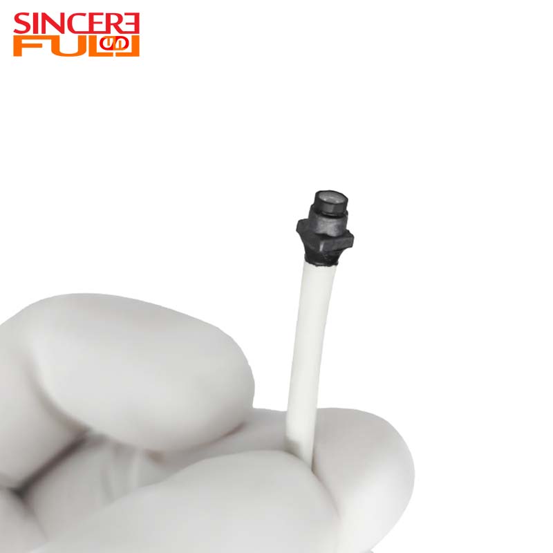
Evaluating ultra-miniature CMOS sensor modules requires looking past marketing hype. Many engineers believe higher megapixels on a module always equal better performance for industrial integration. This myth causes significant engineering headaches. Cramming more pixels onto a tiny module sensor reduces individual pixel size. Smaller pixels capture less light and generate more electronic noise. Low-light performance degrades rapidly as pixel pitch drops below 1.4 microns. You often get clearer, more usable video feeds for your host device from a well-tuned, lower-resolution sensor module. Prioritize pixel size and light sensitivity over raw megapixel counts when selecting your vision component.
Matching your module's optics to the physical inspection distance is critical for integration success.
Matching DOF to inspection distance: A depth of field ranging from 5mm to 50mm works well for modules embedded into tight pipe inspection systems. You must calculate the exact distance between the module's lens and the target surface. Fixed-focus lenses dominate this component space, so getting the focal range wrong renders the integrated module useless.
Addressing edge distortion: Wide-angle macro lenses inherently warp the edges of an image. This "fisheye" effect distorts dimensional measurements on the host software. You must decide whether to correct this distortion at the module level using complex lens stacks or correct it digitally via software calibration on your mainboard.
Lighting remains a massive hurdle when evaluating a compact camera module. Co-locating LEDs right next to the module's image sensor creates immediate integration problems. First, it introduces severe lens glare if the component's isolation barriers fail. Second, high-output LEDs generate substantial heat. This thermal load transfers directly to the CMOS sensor, increasing image noise. Finally, LEDs draw significant power, necessitating thicker wiring from the host board. You must evaluate alternative illumination paths. Ring-light configurations work for wider device tubes. Fiber-optic illumination paths separate the light source from the sensor entirely, eliminating heat at the camera module tip.
Specifying an industrial endoscope camera module requires a realistic approach to ingress protection. Do not blindly request IP68 unless your final integrated device operates continuously underwater. Achieving true IP67 or IP68 ratings at a micro-module scale requires specialized potting compounds and sapphire glass covers on the component. These additions increase unit cost and assembly time. Furthermore, consider chemical resistance. Industrial environments expose the device—and subsequently the internal module—to aggressive solvents, machine oils, and caustic cleaning agents. Ensure your module vendor tests their sealants against the specific chemicals present in your deployment environment.
Many development teams default to a USB endoscope camera module for rapid prototyping. The benefits for component integration are clear and immediate. Universal Video Class (UVC) compliance ensures plug-and-play functionality across various host operating systems. You avoid writing custom component drivers. Integration with a standard PC or Single Board Computer (SBC) takes minutes. However, USB module architectures have strict limitations. Cable length cannot easily exceed two meters without active repeaters on your hardware. Furthermore, USB protocols introduce noticeable latency. This delay makes real-time robotic manipulation frustrating and potentially dangerous.
Bypassing USB for direct-to-SOC module interfaces becomes necessary for advanced hardware integrations. MIPI CSI-2 and DVP module interfaces offer significantly lower latency. They provide raw data access directly to your host system's processor. This architecture reduces the physical footprint at the camera module tip by removing bulky USB bridge chips. However, hidden integration costs lurk in this approach. You must develop custom Linux drivers for the module. You also face complex Image Signal Processor (ISP) tuning on your mainboard. Raw sensor data looks terrible until properly color-corrected and debayered. This tuning process requires specialized imaging engineers to optimize the module's output.
Industrial environments act as massive antennas for electromagnetic interference (EMI). Heavy machinery, servo motors, and high-voltage lines generate intense electrical noise. This noise easily corrupts delicate video signals as they travel from the module to your mainboard over long cable runs. Mitigating EMI requires robust cable shielding on the module's wiring harness. You must utilize twisted-pair wiring and braided copper shields. In some severe cases, optical fiber transmission becomes the only viable solution for the component. Do not underestimate the difficulty of maintaining signal integrity from an embedded module across a noisy factory floor.
Feature Category | USB 2.0 / 3.0 Module Interface | MIPI CSI-2 Module Interface |
|---|---|---|
Integration Speed | Very fast (UVC plug-and-play) | Slow (Requires custom drivers) |
Latency Levels | Moderate to High (Noticeable delay) | Ultra-low (Near real-time) |
Hardware Footprint | Larger (Requires bridge ICs on module) | Minimal (Direct sensor connection) |
ISP Requirements | Handled on-board the camera module | Requires host-side ISP tuning |
Best Use Case | PC-based systems, rapid module PoC | Embedded robotics, AI edge devices |
Standardized modules offer a straightforward path to early hardware validation. Commercial off-the-shelf camera components are best for hardware startups moving quickly. They enable rapid proof-of-concept (PoC) device builds without massive upfront capital. You can test your core software algorithms using available module hardware immediately. However, COTS modules carry distinct integration risks. Suppliers may deprecate the module component without warning. You are also locked into inflexible form factors. The module's focal length and rigid cable routing might barely fit your mechanical design, forcing awkward structural compromises in your final integrated product.
Eventually, production scale and performance demand a transition to custom module hardware. Investing in a purpose-built OEM endoscope camera component solves mechanical friction. You can specify custom lens profiles tailored to your exact host device focal distance. You get specific cable lengths and proprietary connectors that perfectly match your mainboard. This component path incurs Non-Recurring Engineering (NRE) costs for tooling and design time. Yet, these initial component investments improve unit economics at scale. A custom module reduces manual integration and assembly time on your device production line, accelerating overall manufacturing throughput.
Custom module engineering demands realistic project management. You cannot rush optical physics or semiconductor fabrication. Transparent breakdowns of typical module lead times help you avoid missing host product launch windows. Consider the following standard phase durations for module development:
Initial Specification and Optical Design: Takes roughly 3 to 4 weeks. Engineers finalize sensor selection and simulate the module's lens performance.
Custom Tooling and First Articles: Takes 6 to 8 weeks. Factories machine custom module housings and assemble the first component prototype batches.
Sampling and Iterative Validation: Takes 4 to 6 weeks. Your integration team tests the module samples in the host device, identifies thermal or optical flaws, and requests minor component revisions.
Mass Production and Quality Ramping: Takes 4 to 8 weeks after final module approval. The component supplier secures sensor inventory and calibrates end-of-line testing rigs.
Never base your component procurement decisions solely on marketing specifications. OEM buyers must demand raw, unprocessed test images from the module supplier. Request module footage captured in lighting conditions identical to your host application. A spec sheet might claim a 90-degree FOV for the module, but it hides severe chromatic aberration at the edges. Engineering module samples tell the real story. Mount the sample module into your device's mechanical mockup immediately. Observe how the component handles heat dissipation during a two-hour continuous run inside your hardware housing. Real-world physical module validation prevents expensive component mistakes during mass production.
A module supplier can easily build ten perfect samples. Building ten thousand identical module units requires rigorous quality control. You must ask hard questions about their component manufacturing floor. Ask them how they handle sensor binning to ensure consistent low-light performance across all modules. Inquire about their lens alignment tolerances during component assembly. A microscopic shift in lens centering destroys the module's image sharpness. Request their standard operating procedures for end-of-line testing. Every single camera module should pass through an automated optical calibration rig before entering a shipping box to your assembly plant.
Component obsolescence kills hardware products. You must ensure the module vendor guarantees sensor availability for your planned device lifespan. Consumer-grade CMOS sensors utilized in some modules often have a lifecycle of just 18 months. Industrial hardware often requires a five-year lifespan. If the module's sensor goes out of production, you face forced host device redesigns. You will have to rewrite host drivers, re-tune your system's ISP, and alter mechanical device housings. Demand a formal End of Life (EOL) notification policy for the module. Ensure the component supplier offers last-time-buy options to bridge the gap during any future hardware redesign phase.
Navigating global regulatory compliance is incredibly tedious but absolutely necessary for component integration. You must differentiate between compliance at the module component level and your finished product level. A camera module claiming CE or FCC compliance simplifies your final host device certification process. However, the finished host device still requires independent testing. Verify RoHS compliance for all internal solders and adhesives within the module itself. Sourcing non-compliant modules will halt your entire finished product shipment at customs. Secure all module material safety data sheets and certification test reports during the initial component supplier audit.
Successfully integrating a micro-vision module into your hardware system requires a disciplined, sequential approach. Finalize your device's environmental and physical constraints first before looking at embedded sensor modules. Choose your module interface architecture based on your host system’s latency tolerance and processing capabilities. Validate the component's optical performance using raw engineering module samples inside your hardware under real-world lighting conditions. Finally, secure a reliable module supply chain by auditing the component vendor's quality control and lifecycle policies. The clearest next step is to initiate a component hardware trial. We advise engineering teams to request a targeted module evaluation kit (EVK). Ensure this module kit matches your planned host architecture closely, allowing for immediate software integration testing on your mainboard.
A: Standard component ranges vary significantly based on the host application. Embedded modules typically start from 1.0mm for integration into micro-industrial routing systems or veterinary crossover devices. They scale up to 8.0mm or larger for integration into robust inspection hardware where superior lighting and larger internal sensors are required.
A: Thermal management within the component requires multiple integration strategies. Utilize aluminum module housing to aid heat dissipation into the host device frame. Implement pulse-width modulation (PWM) from your mainboard for dynamic LED dimming on the module, which reduces continuous power draw. Finally, rely on thermal throttling algorithms at the sensor level to prevent permanent hardware component damage.
A: Standard USB module protocols suffer severe signal degradation past 2 to 3 meters. Exceeding 5 meters for your component wiring requires active repeater cables to boost the signal to the host. Alternatively, you must switch the module to industrial transmission protocols like FPD-Link or GMSL designed specifically for long-distance internal runs within large machinery.
A: Modules targeted at clinical or veterinary crossover prioritize strict sterilization requirements, bio-compatible component housing, and specific regulatory compliance (like ISO 13485) for integration into advanced tools. They also focus on absolute color reproduction accuracy for tissue analysis. Industrial modules, on the other hand, prioritize component ruggedness, extreme chemical resistance, wider operating temperatures, and overall integration cost-efficiency for heavy hardware deployment.


