Views: 0 Author: Site Editor Publish Time: 2026-11-16 Origin: Site


Hardware engineers and system integrators face a critical bottleneck when embedding vision systems into confined spaces. You must constantly balance miniature module size against reliable data transmission. The widespread adoption of the USB Video Class (UVC) standard has streamlined this integration process. It eliminates frustrating custom driver dependencies and simplifies your software architecture. However, physical integration still carries hidden risks. You must navigate complex hardware constraints to ensure stable, long-term performance. This guide breaks down the technical realities of integrating a USB UVC endoscope camera module. We focus heavily on interface selection, power constraints, and OS-level compatibility. You will learn how to manage thermal output, evaluate connector durability, and select the right protocols. These practical insights ensure scalable, compliant product rollouts for both medical and industrial applications.
Driverless Deployment: UVC compliance ensures plug-and-play functionality across major operating systems (Windows, Linux, Android), drastically reducing software development overhead.
Interface Trade-offs: While a USB2.0 UVC camera module offers universal legacy support, transitioning to a Type-C camera module provides superior power delivery and reversible connector advantages for modern host devices.
Thermal Management is Critical: Micro-lenses and localized Image Signal Processors (ISPs) generate heat; power draw must be tightly managed to prevent thermal throttling in medical or industrial applications.
Cable Length Limitations: Standard USB interfaces suffer signal degradation beyond 2–3 meters, requiring active repeaters or alternative signaling for deep-insertion endoscope designs.
Custom camera drivers introduce significant maintenance debt over a product lifecycle. They create OS update vulnerabilities and complex compliance hurdles. UVC standardizes the video payload to solve these fundamental issues. It allows the host system to recognize the camera hardware automatically. This standardization removes the need for proprietary software installations. Your end-users experience a true plug-and-play setup.
We must detail the distinct UVC advantage here. The UVC protocol interfaces natively into host system application programming interfaces (APIs). On Windows machines, it uses DirectShow or Media Foundation frameworks. On Linux distributions, it leverages Video4Linux2 (V4L2). This native integration ensures seamless communication between the hardware and the operating system. You avoid the headache of rewriting custom drivers for every minor OS update.
A successful integration achieves specific, measurable performance metrics. You need stable frame rates and exceptionally low latency. Accurate color reproduction is also vital for diagnostic or inspection tasks. The system must deliver these results consistently. It should never require end-user software troubleshooting. Plug-and-play reliability ultimately defines a successful module deployment.
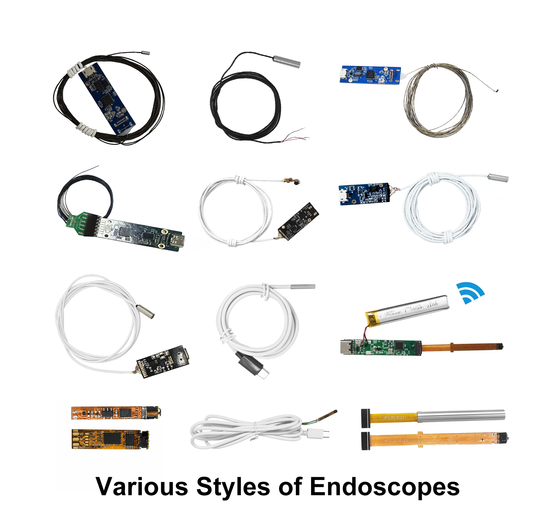
Choosing the right physical interface dictates your product's compatibility and long-term performance. You must carefully weigh legacy support against modern power delivery standards.
The USB2.0 UVC camera module remains the undisputed industry standard for baseline endoscope designs. It typically supports 720p or 1080p resolutions streaming at 30 frames per second. This interface offers unmatched universal compatibility across older medical carts and legacy industrial terminals.
However, you must consider strict bandwidth limitations. USB 2.0 provides a theoretical maximum of 480 Mbps. In practice, you only achieve about 300 Mbps of usable throughput. This restriction forces the mandatory use of compression formats like MJPEG or YUY2. MJPEG drastically reduces bandwidth requirements but introduces slight processing latency. YUY2 offers uncompressed, raw frames but significantly lowers the maximum achievable frame rate. You must balance these engineering trade-offs based on your application's real-time visual requirements.
Modern handheld diagnostics increasingly rely on the Type-C camera module. It integrates perfectly into mobile-tethered industrial scopes and modern clinical tablets. The reversible connector greatly improves the user experience in fast-paced clinical environments. It eliminates insertion errors during critical procedures.
Physical footprint presents a unique design challenge here. Routing Type-C connections inside tight enclosures requires careful PCB layout planning. Sometimes, using bare 4-pin or 5-pin layouts on the PCB level works better. You can hardwire the module internally while exposing a standard Type-C port externally. This approach saves precious internal space while maintaining modern external connectivity. It offers the best of both worlds for compact device designs.
Endoscopes endure repeated bending and highly hostile environments daily. You must rigorously evaluate mating cycles for any exposed external connectors. Mechanical strain relief is absolutely critical where the cable meets the camera head. A common mistake is underspecifying the strain relief boot. Poor strain relief inevitably leads to premature signal failure and costly repairs. Best practice dictates utilizing over-molded connectors and high-flex cables. These materials protect the delicate internal wiring from harsh mechanical stress and prevent moisture ingress.
Endoscope cameras pack dense, complex electronics into microscopic spaces. This physical density makes power management and thermal dissipation your top engineering priorities.
USB power delivery follows very specific protocols in UVC modules. Most endoscope modules require a highly steady 5V supply line. However, the actual current draw fluctuates significantly during active operation. LED illumination pulls variable current based on specific brightness settings. The internal Image Signal Processor (ISP) also draws heavy power during complex image rendering. You must ensure the host device can comfortably supply stable peak current. Sudden voltage drops will cause the camera to disconnect randomly.
High-resolution sensors housed in sub-5mm diameters generate rapid, intense heat. The tiny surface area simply cannot dissipate this thermal energy quickly enough. This trapped heat poses severe risks in actual field applications. A common mistake is completely ignoring the localized heat generated by the ISP.
In medical settings, exceeding strict thermal limits can cause severe patient tissue damage. Regulatory bodies heavily monitor and restrict endoscope tip temperatures. In industrial inspections, excessive heat introduces severe sensor noise into the image. This thermal noise degrades image clarity and hides critical inspection flaws.
You must proactively implement robust cooling strategies during the design phase. Hardware-level solutions include using conductive copper shielding to spread localized heat. Duty-cycling the LEDs reduces continuous power draw and actively lowers temperatures.
Firmware adjustments also play a major role in thermal control. Capping frame rates actively prevents the ISP from overworking. You can program thermal safety cutoffs directly into the device firmware. These combined approaches effectively maintain safe operating temperatures under continuous use.
Apply copper tape or thermally conductive potting to spread localized heat evenly.
Implement PWM (Pulse Width Modulation) to duty-cycle LED brightness efficiently.
Throttle ISP processing by capping maximum frame rates directly in the firmware.
Design automatic thermal shutdown routines to protect sensitive tissues and electronics.
A USB endoscope camera module must communicate flawlessly across diverse host systems. UVC provides the necessary baseline, but each OS handles the protocol differently.
Different operating systems require highly specific integration approaches. You must exhaustively test your module across all intended target platforms.
Windows: Integration is generally seamless via Media Foundation or DirectShow APIs. However, OEM-specific image tuning often requires specialized UVC extension units to access advanced features.
Linux: Native V4L2 support makes Linux ideal for embedded IoT systems. It powers many Raspberry Pi-driven medical gateways and rugged edge diagnostic tools.
Android: Android integration requires explicit OTG (On-The-Go) hardware support. Users need standard UVC applications to view the live video feed. Field experience reveals Android OTG implementation varies wildly between different handset manufacturers. You must watch out for severe fragmentation risks across different Android hardware layers.
Standard UVC strictly covers basic video streaming capabilities. But what if you need custom hardware controls? UVC Extension Units (XUs) solve this specific engineering problem. XUs allow integrators to access proprietary camera controls safely within the standardized framework.
You can map specific LED toggles or autofocus triggers directly to XU commands. This method keeps the device completely driverless while unlocking advanced functionality. It gives your software team a highly standardized API to control custom hardware features reliably.
Selecting the perfect module requires a highly structured evaluation framework. You must perfectly align technical specifications with your desired clinical or industrial outcomes.
Match your specific resolution needs tightly with available interface bandwidth. Do not specify uncompressed 1080p over USB 2.0 if low latency is mission-critical. The bandwidth bottleneck will inevitably cause severe, unusable video lag.
You must define Depth of Field (DoF) and Field of View (FoV) accurately. Base these critical requirements on your specific inspection target distance. A wide FoV works brilliantly for general cavity overviews. Conversely, a narrow FoV suits highly detailed, close-up defect inspections.
Assess the vendor's proven ability to customize the ISP tuning parameters. Features like Auto White Balance and Auto Exposure need highly specific calibration. Reflective metal pipes require vastly different tuning profiles than organic human tissue.
Check for comprehensive EMI/EMC compliance documentation early in the process. This paperwork is especially critical for stringent medical device certification, such as IEC 60601. Without it, your final product will definitely fail regulatory clearance testing.
Evaluation Criteria | Industrial Application Focus | Medical Application Focus |
|---|---|---|
ISP Tuning | Aggressive glare reduction for highly reflective metals | Exceptional high color fidelity for tissue differentiation |
Compliance | Standard CE/FCC, rugged IP67+ waterproof ratings | Strict IEC 60601, mandatory biocompatibility standards |
Thermal Limit | Moderate limits (primary focus on sensor noise reduction) | Extremely strict (must stay well below tissue damage thresholds) |
Always recommend starting your project with standard vendor evaluation kits. These kits let you test OS compatibility and establish a reliable thermal baseline. Do this crucial testing before committing to custom PCB shapes or specialized cable lengths. Early testing clearly reveals hidden integration roadblocks. It ultimately saves your team months of costly hardware revisions.
Integrating a UVC-compliant camera module drastically simplifies your overall software architecture. It completely removes the heavy burden of maintaining custom drivers across disparate operating systems. However, this driverless convenience requires highly rigorous upfront hardware validation. You must meticulously verify physical interfaces, power budgets, and thermal dissipation limits.
Prioritize vendors who willingly offer highly transparent engineering documentation. Look for proactive partners providing modular evaluation kits for early prototyping. Ensure they possess the technical capability to customize UVC Extension Units for specialized hardware controls. Taking these proactive steps ensures your endoscope system performs reliably in the most demanding environments.
A: Passive USB 2.0 cables typically max out at 5 meters. For endoscopes requiring longer reaches, active repeater cables or converting the signal to a different protocol (like MIPI or Ethernet) at the handle is necessary.
A: No. If the Type-C camera module is UVC compliant, the connector type (Type-C) only dictates the physical and electrical delivery, not the software protocol. It will utilize native OS drivers.
A: Yes, typically using the YUY2 format, but it is heavily restricted by USB 2.0 bandwidth. Uncompressed 1080p is usually limited to 5-10 fps, which is why MJPEG compression is standard for smooth 30fps streaming.
A: LED control is typically handled either through a physical inline hardware dimmer on the USB cable, or via software using UVC Extension Units (XUs) programmed into the module's firmware.


