Views: 0 Author: Site Editor Publish Time: 2026-07-13 Origin: Site


Missed defects in aerospace, automotive, and precision manufacturing often lead to catastrophic financial and operational losses. A microscopic fracture in an engine block or a hidden burr inside a hydraulic valve can halt entire production lines. To combat these critical risks, modern industries rely heavily on advanced non-destructive testing (NDT). We are witnessing a massive shift from off-the-shelf inspection tools to highly specialized, purpose-built diagnostic equipment integrated with custom camera modules. Selecting the right borescope camera module requires balancing strict physical constraints, optimal optical clarity, and robust integration architecture. You must align these factors closely to ensure reliable, compliant decision-making in critical environments. In this article, you will learn how to accurately define precision success criteria. We will explore the functional differences between standardized UVC interface modules and bare-board custom engineering options. Finally, you will discover a structured methodology to shortlist and pilot test the best endoscope camera module for your specific integration needs.
Sub-2mm and articulating modules are essential for complex geometries but require trade-offs in image sensor size and illumination.
Selecting between an OEM borescope module and a standard plug-and-play UVC module dictates your engineering overhead and software control.
Reliable precision inspection relies heavily on thermal management, lens focal depth, and consistent IP-rated environmental protection for the integrated module.
Modern manufacturing demands rigorous quality control. We must move beyond simply seeing inside a cavity. Precision engineering requires us to measure dimensions accurately, categorize microscopic flaws, and eliminate false positives during automated inspections. You cannot afford to misinterpret a shadow as a structural crack. Achieving this level of precision requires a complete reevaluation of your imaging module integration.
Physical access constraints dictate your baseline module requirements. Evaluating entry port diameters determines the maximum allowable size of your camera tip. For instance, micro-machinery and medical device prototyping often necessitate 1.6mm ultra-flexible cables. You cannot force a standard 4mm camera module into a 2mm micro-valve without risking severe damage to both the component and the testing equipment.
Industrial applications also present severe environmental hazards. You must assess the module's survivability across multiple stress vectors. Consider the following environmental challenges:
Prolonged exposure to industrial solvents, such as aviation Skydrol or automotive brake fluids.
Extreme temperature fluctuations inside recently fired combustion chambers.
High-pressure environments found deep within hydraulic cylinders and manifolds.
Furthermore, compliance and audit trails drive camera module selection in regulated sectors. Verifiable image capture plays a vital role in meeting strict ISO guidelines and industry-specific safety standards. Aerospace engineers operating under AS9100 standards require modules capable of capturing uncompressed, time-stamped visual data to prove compliance during rigorous safety audits.
Navigating the hardware landscape means understanding the fundamental differences between bare-board components and standardized interface modules. Your choice directly impacts deployment speed and engineering resource allocation when building industrial endoscope equipment.
An OEM borescope module consists of bare-board or semi-housed camera sensors designed for native integration into proprietary hardware. These units lack consumer-friendly outer casings and standardized software interfaces. They are strictly positioned as core components best suited for custom manufacturing equipment, specialized robotics, and bespoke medical device prototyping.
The implementation reality involves high upfront engineering costs. Your development team must handle custom MIPI tuning, design dedicated image signal processors (ISPs), and manufacture custom protective housing. However, this route grants you absolute control over raw data output and physical module dimensions.
In contrast, a USB borescope camera offers a standardized, UVC-compliant module ready for immediate software interfacing. You plug it into a standard terminal, and the operating system recognizes the video feed instantly. These modules are ideal for rapid integration into quality assurance bays, automated diagnostic systems, and PC-based inspection stations.
While this approach significantly lowers engineering friction, it limits your customization capabilities. You generally cannot alter the raw data output, and you must accept the manufacturer's physical form factor and predefined software compression algorithms.
Mechanical realities govern the choice between fixed and moving lenses. Modules featuring two-way and four-way articulation mechanisms solve complex blind-spot challenges found inside complex metal castings or automotive engine cylinders. Integrating these allows automated systems or operators to steer the distal tip to look backwards at valves or maneuver around tight internal corners.
However, articulation introduces unavoidable mechanical failure points. Tension wires stretch over time, and microscopic hinges wear down under constant industrial use. We recommend carefully weighing the necessity of steering against the extended durability provided by rigid, fixed-lens module alternatives.
Camera Module Architecture Comparison Matrix
Module Type | Primary Integration Use Case | Engineering Overhead | Data Customization Level |
|---|---|---|---|
OEM Bare-Board | Robotics, Automated Testing | High (Requires ISP tuning) | Maximum |
UVC Plug-and-Play Module | System Integration, PC Diagnostics | Low (Standard drivers) | Limited |
Articulating Lens Module | Complex Cavities, Blind Spots | Medium (Mechanical care) | Variable |
Fixed Rigid Lens Module | Straight Pipes, High Durability | Low (No moving parts) | Variable |
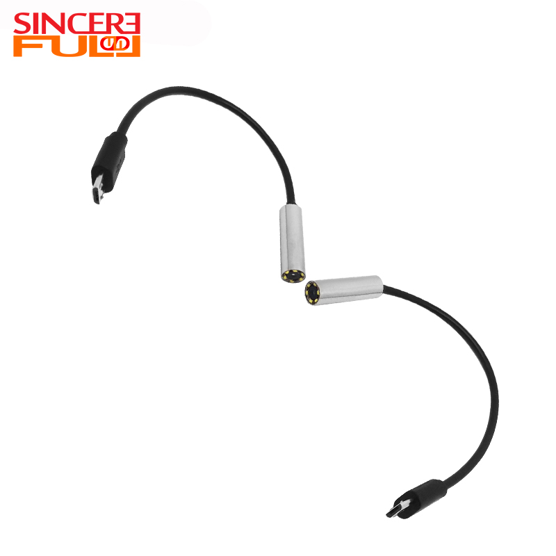
Evaluating a precision borescope camera for OEM integration requires a deep understanding of optical physics. You must balance the physical limitations of micro-sensors against your need for pristine image clarity.
The physics of miniaturization dictate strict boundaries. A compact borescope inspection module measuring under 3mm typically utilizes smaller CMOS sensors ranging from 0.16MP to 1MP. You cannot fit a massive multi-megapixel sensor into a 2mm tip without increasing the diameter or sacrificing vital illumination space.
When resolution remains hardware-limited, you must maximize image contrast. High-quality micro-lenses and advanced software algorithms help edge-enhance the video feed. This ensures your integrated equipment can still identify micro-fractures even when operating below the 1MP threshold.
Optical clarity depends entirely on matching your focal range to the specific inspection cavity. A camera module tuned for a 5mm to 50mm focal depth will render objects beautifully inside a narrow tube but will blur entirely inside a large storage tank.
Best Practice: Always baseline your required field of view against the narrowest segment of your inspection path. Pushing a wide-FOV lens into a highly constrained pipe causes severe edge distortion, commonly known as the fish-eye effect, which ruins dimensional accuracy for automated tools.
Lighting remains the most critical factor in internal imaging. You must evaluate ring LED density and placement on the module. Too few LEDs create dark spots, while poorly angled lights cause blinding reflections. Fiber-optic light guides offer an excellent alternative, transmitting intense light from a remote source to keep the camera module tip compact and cool.
Highly reflective metallic surfaces pose a unique challenge. Machined steel and aluminum bounce light directly back into the sensor. You should seek modules featuring specialized glare-reduction algorithms or polarized lens coatings to mitigate these intense reflections.
Material engineering determines how easily your endoscope equipment can navigate internal structures. You constantly face friction between flexibility and pushability. "Ultra-flexible" cables excel at navigating tight, curved pipes but often fail when you try to push them across open voids. They sag and lose direction.
Conversely, rigid or semi-rigid tungsten-braided tubes cross open spaces easily but cannot round sharp corners. You must map your operational geometry precisely to select the correct insertion tube stiffness for your module.
Integrating these sophisticated endoscope camera modules into daily operations or custom equipment exposes hidden technical risks. You must proactively manage physical and digital friction points to maintain system reliability.
Thermal output at the distal tip requires strict management. High-intensity LEDs generate significant heat within confined spaces. If poorly dissipated, this heat bleeds into the CMOS sensor, causing thermal noise. This noise manifests as visual graininess, which automated inspection algorithms frequently misclassify as surface defects. Furthermore, excessive heat damages temperature-sensitive components inside aerospace assemblies during prolonged inspections.
Software and ISP calibration present another substantial hurdle for OEMs. Automated inspection environments demand stable color rendering and zero latency. Color drift over time forces teams to recalibrate their AI recognition models constantly. Image stitching requirements add further complexity, demanding precise synchronization between physical module movement and software capture rates.
Durability dictates realistic lifecycle expectations. Industrial environments show no mercy to delicate optics. Articulating joints snap under aggressive handling, and unprotected lenses suffer deep scratches from metal burrs. You must invest in sapphire glass lens covers and enforce strict handling protocols to ensure daily industrial use does not destroy your integrated camera modules.
Supply chain verification remains crucial for long-term projects. Integrating a specific sensor module into proprietary robotics requires absolute component stability. You must ensure consistent component availability from your manufacturer. Demand strict revision control agreements to prevent sudden, unannounced hardware changes. A minor undocumented shift in the sensor's firmware can instantly break your entire custom software stack.
Selecting the final camera module requires a structured, empirical approach. Do not rely solely on marketing brochures. Follow this disciplined logic to move from theoretical evaluation to a functional proof of concept.
Baseline the Physical Specs: Filter your initial module options strictly by maximum allowable diameter and minimum required flexibility. Discard any unit failing these non-negotiable physical dimensions.
Request Sample Image Data: Demand raw, uncompressed, and unedited footage from the specific camera module you intend to buy. Ask the vendor to capture materials similar to your use case, such as polished steel, matte carbon fiber, or reflective aluminum.
Evaluate Vendor Engineering Support: Assess the manufacturer’s technical agility for module integration. Determine their ability to provide custom lens viewing angles, specific cable lengths, and comprehensive API/SDK documentation for your software team.
Pilot Testing: Run a controlled trial focused aggressively on integration failure replication. Do not merely test for ideal-condition performance. Push the hardware module to its thermal and physical limits to see exactly how and when it fails in your specific environment.
Precision internal inspection demands rigorous alignment between physical module constraints, optical capabilities, and your chosen equipment integration architecture.
Balancing environmental survivability, focal depth, and illumination quality ensures your inspection module's data remains accurate and legally compliant.
Mechanical realities dictate your operational workflows. Articulation modules provide superior access but demand careful handling compared to robust fixed-lens components.
Ultimately, avoid over-indexing on raw megapixel counts. A high-resolution sensor module fails entirely without proper lighting and focal suitability. Prioritize robust illumination architectures, precise focal depths, and mechanical reliability to secure measurable operational ROI. Engage your core engineering team immediately to request detailed technical spec sheets, and initiate a rigorous pilot test modeled on your most challenging module integration geometry.
A: Current micro-sensor technology allows module diameters as small as 1.0mm to 1.6mm. Navigating this scale requires significant trade-offs. You gain unparalleled access into micro-machinery but sacrifice internal illumination space and image resolution. Engineers typically integrate 0.16MP sensors at this scale. You must rely on minimal LED configurations, making these modules best suited for highly controlled, close-proximity inspections.
A: USB 2.0 bandwidth often introduces slight video latency. UVC driver efficiency compresses data, creating micro-delays between physical module movement and screen display. This latency rarely impacts standard optical monitoring. However, zero-latency robotic applications require raw MIPI connections. MIPI bypasses USB compression overhead, feeding raw sensor data directly from the camera module into a dedicated image signal processor for real-time analysis.
A: Yes, provided the integrated module carries a verified IP67 or IP68 rating. Industrial camera modules designed for automotive environments utilize chemical-resistant sheathing. Tungsten braiding provides excellent abrasion resistance, while specialized coatings protect internal module wiring from brake fluids, synthetic oils, and industrial solvents. Always verify the specific chemical resistance chart before OEM deployment.
A: Yes. Articulating modules rely on internal tension wires and microscopic joints to navigate complex geometries. These mechanical components suffer from repetitive stress and friction, leading to inevitable wear. You can mitigate failure rates through rigorous preventive maintenance. In highly repetitive, automated environments, engineers often opt for integrating multiple fixed-angle camera modules instead to eliminate moving parts entirely.


